Recruiting Display
From MFIWiki
Recruiting Display
 |
 | |
 |
 |
Display Concept
Like anything, a good plan is required for any job. I started with drawing out a concept of what I wanted and how it should look. Here is a PDF of the concept. I even cut out my paper concept and pieced it together to see what the model would like. A 3D representation is always good for visualization
|
Materials

|
Materials are pretty easy. I bought some standard plywood (two 8x12's). I can post the dimensions of the pieces later. Just cut the pieces accordingly (at Home Depot or lumber store preferably - let them do all the work). When you get home, you have all the pieces that require minimal cutting and assembly. |

Construction
First step is to cut the sides down to something that is "Trek-ish" in shape. I am loosely basing my design on a computer console from the bridge of Voyager. Here is one side drawn with the shape.
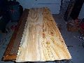

Side one is cut and side two is placed below to draw its shape over the side two.
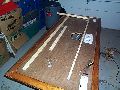

Here is the top of the display being framed. This box is made of four cut 2x2's and pieced together with corner brackets. This frame will be placed at the top and the plexiglas (painted up later) attached to it.
File:Dcp00196.jpg
Close up of the frame. Nails are good to assemble things, but screws serve much better for sturdiness and if you need to completely break it down, they can be backed out and re-assembled later.
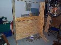

Jumping ahead a little here. The sides are attached to the top box frame. The middle piece which will serve as keyboard shelf is attached as is the bottom piece which is angled slightly from the middle to the bottom again for a "Trek-ish" look.

The keyboard rest is slid into place. Two small pieces of wood are screwed into the side so the keyboard rest slides in. The nice thing about this display is that it can be completely broken down and stored for transport totally flat.
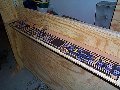

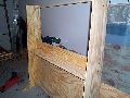
Okay... now you have to get creative. I printed up six pages of LCARS type controls as seen from Voyager and taped them end to end. This printout will be taped to the back of a piece of plexiglass to make the keyboard. The edges of the plexiglass that aren't covered by the cutout will be painted black. This allows for a glossy outer layer as your cutout and black paint are on the inner layer. I'll post the graphics so you don't have to redo them, or you can alter them as you see fit.
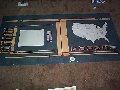

The Main Display is a bit tougher. It is huge and you have to piece together your printouts and disperse them throughout the plexiglass. I took this from the Voyager Tactical Display. One side has a white cutout which reserves the space for the television to be placed up against the plexiglass from the back. The other side has a USA map to denote chapter locations. Both sides can be done as I did the left to allow for two TV's/computer, or one of each. The point is to make it multimedia where it attracts attention.
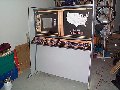

Okay. I got carried away and didn't take any more pictures until now (blush). Well, here is the display once the graphics are applied. I disassembled the display after the last stage and painted the entire visible surface gray. After two coats of paint, I took some silver packing tape and began to edge the display.
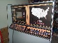

Edging the display accomplishes two things. It not only looks good, but it eliminates the edges of the wood making it more smooth looking prop. The contrast color also makes it appear as if it is made of two materials. Again, it looks good (grin).
| Lumber $45 |
| Plexiglass Back $15 |
| Bolts and Nuts $25 |
| Plexiglass Keyboard $10 |
| Paint/Tape $30 |